The PCB contains just 2 components:
1. 10uF electrolytic capacitor
Make sure you insert this component with the positive lead (the long wire) facing right, with the strip on the body facing left. Push it most of the way into the PCB.
2. M66T IC
This has 3 wires. Spread the wires slightly and insert it with the flat
part of the case facing left. Push it about halfway into the PCB
CONNECTING THE SPEAKER
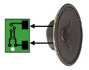
Now connect 2 solid core wires of about 30mm in length to the speaker terminals. Solder the other end to the large copper pads on the underside of the PCB.
You will need to either cut the positive lead, or add another wire to link the micro switch to the PCB. It depends how much wire you need.
Connect the power leads by feeding them up through the large hole first, then through the smaller holes.
1. 10uF electrolytic capacitor
Make sure you insert this component with the positive lead (the long wire) facing right, with the strip on the body facing left. Push it most of the way into the PCB.
2. M66T IC
This has 3 wires. Spread the wires slightly and insert it with the flat
part of the case facing left. Push it about halfway into the PCB
CONNECTING THE SPEAKER
Now connect 2 solid core wires of about 30mm in length to the speaker terminals. Solder the other end to the large copper pads on the underside of the PCB.
POWER SUPPLY
Left shows how to connect the battery, switch and PCB together.You will need to either cut the positive lead, or add another wire to link the micro switch to the PCB. It depends how much wire you need.
Connect the power leads by feeding them up through the large hole first, then through the smaller holes.


No comments:
Post a Comment