Currency Converter

  • This is default featured slide 1 title

    Go to Blogger edit html and find these sentences.Now replace these sentences with your own descriptions.This theme is Bloggerized by Lasantha Bandara - Premiumbloggertemplates.com.

  • This is default featured slide 2 title

    Go to Blogger edit html and find these sentences.Now replace these sentences with your own descriptions.This theme is Bloggerized by Lasantha Bandara - Premiumbloggertemplates.com.

  • This is default featured slide 3 title

    Go to Blogger edit html and find these sentences.Now replace these sentences with your own descriptions.This theme is Bloggerized by Lasantha Bandara - Premiumbloggertemplates.com.

  • This is default featured slide 4 title

    Go to Blogger edit html and find these sentences.Now replace these sentences with your own descriptions.This theme is Bloggerized by Lasantha Bandara - Premiumbloggertemplates.com.

  • This is default featured slide 5 title

    Go to Blogger edit html and find these sentences.Now replace these sentences with your own descriptions.This theme is Bloggerized by Lasantha Bandara - Premiumbloggertemplates.com.

UM66T MELODY IC

 The PCB contains just 2 components:


1. 10uF electrolytic capacitor
Make sure you insert this component with the positive lead (the long wire) facing right, with the strip on the body facing left. Push it most of the way into the PCB.

2. M66T IC
This has 3 wires. Spread the wires slightly and insert it with the flat
part of the case facing left. Push it about halfway into the PCB


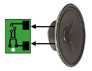
CONNECTING THE SPEAKER


Now connect 2 solid core wires of about 30mm in length to the speaker terminals. Solder the other end to the large copper pads on the underside of the PCB.

POWER SUPPLY
 Left shows how to connect the battery, switch and PCB together.
You will need to either cut the positive lead, or add another wire to link the micro switch to the PCB. It depends how much wire you need.
Connect the power leads by feeding them up through the large hole first, then through the smaller holes.

Share:

TOUCH SWITCHS

TOUCH SWITCH 1

This circuit detects the skin resistance of a finger to deliver a awfully tiny current to the super-alpha try of transistors to show the circuit ON. The output of the "super transistor" activates the BC 557 transistor. The voltage on the highest of the world is passed to the front of the circuit via the 4M7 to require the place of your finger and also the circuit remains ON.

To turn the circuit OFF, a finger on the OFF pads can activate the primary transistor and this may rob the
"super transistor" of voltage and also the circuit can close up.

TOUCH SWITCH 2

This circuit detects the skin resistance of a finger to show the circuit ON for concerning one second. The output are often taken to a counting circuit. The circuit consumes no current when in quiescent mode:

Share:

Flag

free counters

Popular Posts

CLOCK

TOTAL VISITORS

ONE

Google Map

Recent Posts

Unordered List

  • Lorem ipsum dolor sit amet, consectetuer adipiscing elit.
  • Aliquam tincidunt mauris eu risus.
  • Vestibulum auctor dapibus neque.

Pages

Theme Support

Need our help to upload or customize this blogger template? Contact me with details about the theme customization you need.