Currency Converter

  • This is default featured slide 1 title

    Go to Blogger edit html and find these sentences.Now replace these sentences with your own descriptions.This theme is Bloggerized by Lasantha Bandara - Premiumbloggertemplates.com.

  • This is default featured slide 2 title

    Go to Blogger edit html and find these sentences.Now replace these sentences with your own descriptions.This theme is Bloggerized by Lasantha Bandara - Premiumbloggertemplates.com.

  • This is default featured slide 3 title

    Go to Blogger edit html and find these sentences.Now replace these sentences with your own descriptions.This theme is Bloggerized by Lasantha Bandara - Premiumbloggertemplates.com.

  • This is default featured slide 4 title

    Go to Blogger edit html and find these sentences.Now replace these sentences with your own descriptions.This theme is Bloggerized by Lasantha Bandara - Premiumbloggertemplates.com.

  • This is default featured slide 5 title

    Go to Blogger edit html and find these sentences.Now replace these sentences with your own descriptions.This theme is Bloggerized by Lasantha Bandara - Premiumbloggertemplates.com.

5 channel radio remote control

TX-2B / RX / 2B  5 channel radio remote control.

This article is about a simple 5 channel radio remote control circuit based on ICs TX-2B and RX-2B from Silan Semiconductors. TX-2B / RX-2B is a remote encoder decoder pair that can be used for remote control applications. TX-2B / RX-2B has five channels, wide operating voltage range (from 1.5V to 5V), low stand by current (around 10uA), low operating current (2mA), auto power off function and requires few external components. The TX-2B / RX-2B was originally designed for remote toy car applications, but they can be used for any kind of remote switching application.

Circuit diagrams and description.

Remote encoder / transmitter circuit.


The TX-2B forms the main part of the circuit. Push button switches S1 to S5 are used for activating (ON/OFF) the corresponding O/P channels in the receiver / decoder circuit. These push button switches are interfaced to the built-in latch circuitry of the TX-2B. Resistor R7 sets the frequency of the TX-2B’s internal oscillator. Resistor R1 and Zener diode D1 forms a simple Zener regulator circuit for providing the IC with 3V from the 9V main supply. C2 is the filter capacitor while C1 is a noise by-pass capacitor. D2 is the power on indicator LED while R6 limits the current through the same LED. S1 is the ON/OFF switch. The encoded control signal will be available at pin 8 of the IC. The encoded signal available at pin 8 is without carrier frequency. This signal is fed to the next stage of the circuit which is a radio transmitter. Crystal X1 sets the oscillator frequency of the transmitter section. R2 is the biasing resistor for Q1 while R3 limits the collector current of Q1. The encoded signal is coupled to the collector of Q1 through C3 for modulation. Transistor Q2 and associated components provide further amplification to the modulated signal.

Remote receiver / decoder circuit.


The remote receiver circuit is built around the IC RX-2B. The first part of the circuit is a radio receiver built around transistor Q1. The received signal is demodulated and fed to pin 14 of the IC. Pin 14 is the input of the built in inverter inside the IC. R2 sets the frequency of the IC’s internal oscillator. O/P 1 to O/5 are the output pins that are activated corresponding to the push buttons S1 to S5. Zener diode D1 and resistor R12 forms an elementary Zener regulator for supplying the RX-2B with 3V from the 9V main supply. C12 is the filter capacitor while R11 is the current limiter for the radio receiver section. Diode D2 protects the circuit from accidental polarity reversals. C15 is another filter capacitor and C14 is a noise by-pass capacitor.

Notes.

§  This circuit can be assembled on a vero board or a PCB.
§  Use 9V DC for powering the transmitter / receiver circuits.
§  Battery is the better option for powering the transmitter / receiver circuit.
§  If you are using a DC power supply circuit, it must be well regulated and free from any sort of noise.
§  Both ICs must be mounted on holders.

Interfacing relay to the RX-2B output.

The method for interfacing a relay to the output of RX-2B is shown below. When push button switch S1 of the transmitter circuit is pressed, pin O/P1 (pin 7 of the RX-2B) goes high. This makes the transistor 2N2222 to conduct and the relay is activated. The same technique can be applied to other output pins of the RX-2B. The relay used here is a 200 ohm type and at 9V supply voltage the load current will be 45mA which is fine for 2N2222 whose maximum possible collector current is 900mA. When using relays of other ratings this point has to be remembered and do not use a relay that consumes a current more than the maximum possible collector current of the driver transistor.


Share:

Seven Segment Counter Display Circuit

Here is the circuit diagram of a seven segment counter based on the counter IC CD 4033.This circuit can be used in conjunction with various circuits where a counter to display the progress  adds some more attraction.
IC NE 555 is wired as an astable multivibrator for triggering the CD 4033.For each pulse the out put of CD 4033 advances by one count.The output of CD 4033 is displayed by the seven segment LED display LT543.Switch S1 is used to initiate the counting.Diode D1 prevents the risk of accidental polarity reversal.

Seven Segment Circuit Diagram with Parts List.


Share:

IR Burglar Alarm for Basic Home security system

IR based entry detector alarm is useful for someone crosses the Gate or door of house when is left open.. It can alarm you and notify you that someone entered into the door or place.. This project will be used at Doors/ Entrance of office to get alert the owner or admin to notify someone crossed the gate or door of the location.


IR LED will send and receives signal when some one interrupts the IR signal alarm will be started to make alert of any burglar or theft.

 
Share:

Cable LAN Tester Circuit


Here iscable LAN testercircuit. Thecable LAN testercircuit can also to test cable on telephone, coaxial cable, Lan cable and other. Thiscable LAN testercircuit using led for main indicator device. This simple cable LAN tester circuit, can be make in home. Designed initially for my intercom, but can be used with alarm wiring, CAT 5 cables and more. As the 4017 has limited driving capabilities, then each output is buffered by a 4050. This provides sufficient current boost for long cables and the transmitter and receiver LED's. The receiver is simply 8 LED's with a common wire…read on. The cable LAN tester circuit comprises transmitter and receiver, the cable under test linking the two. The transmitter is nothing more than a "LED chaser" the 4011 IC is wired as astable and clocks a 4017 decade counter divider. The 4017 is arranged so that on the 9th pulse,the count is reset. Each LED will light sequentially from LED 1 to LED 8 then back to LED 1 etc. Note also that as the CMOS 4050 is only a hex buffer, you need 8 gates so two 4050′s are required, the unused inputs are connected to ground (battery negative terminal). Please note that for clarity this cable LAN tester?circuit has been drawn without showing power supplies to the CMOS 4011 and CMOS 4050 IC’s. The positive battery terminal connects to Pin 14 of each IC and negative to Pin 7. The CMOS 4017 uses Pin 16 and Pin 8 respectively.
Share:

Mobile incoming call indicator


Description.
This circuit can be used to escape from the nuisance of mobile phone rings when you are at home. This circuit will give a visual indication if placed near a mobile phone even if the ringer is deactivated.
When a call is coming to the mobile phone, the transmitter inside it becomes activated. The  frequency of the transmitter is around 900MHz.The  coil L1 picks up these oscillations by induction and feds it to the base of Q1. This makes the transistor Q1 activated.Since the Collector of Q1 is connected to the pin 2 of IC1 (NE555) , the IC1 is triggered to make the LED connected at  its output pin (pin 3) to blink. The blinking of the LED is the indication of incoming call.

Circuit diagram with Parts list. 
Notes. 
  • The coil L1 can be made by making 150 turns of 36 SWG enameled copper wire on a 5mm dia plastic former.Or you can purchase a 10 uH coil from shop if available.
  • The circuit can be powered from a 6V battery.
  • Assemble the circuit on a good quality PCB.
  • C1 & C3 are to be polyester  capacitors.
  • The electrolytic capacitor C2 must be rated 10V.

Share:

Static 0 to 9 display

Description.
The circuit shown here is of a simple 0 to 9 display that can be employed in a lot of applications. The circuit is based on asynchronous decade counter 7490(IC2), a 7 segment display (D1), and a seven segment decoder/driver IC 7446 (IC1).
The seven segment display consists of 7 LEDs labelled ‘a’ through ‘g’. By forward biasing different LEDs, we can display the digits 0 through 9. Seven segment displays are of two types, common cathode and common anode. In common anode type anodes of all the seven LEDs are tied together, while in common cathode type all cathodes are tied together. The seven segment display used here is a common anode type .Resistor R1 to R7 are current limiting resistors. IC 7446 is a decoder/driver IC used to drive the seven segment display.
Working of this circuit is very simple. For every clock pulse the BCD output of the IC2 (7490) will advance by one bit. The IC1 (7446) will decode this BCD output to corresponding the seven segment form and will drive the display to indicate the corresponding digit.

Circuit diagram.


Notes.

§  The circuit can be assembled on a perf board.
§  Use 5V DC for powering the circuit.
§  The clock can be given to the pin 14 of IC2.
§  D1 must be a seven segment common anode display.
§  All ICs must be mounted on holders.

Share:

UM66T MELODY IC

 The PCB contains just 2 components:


1. 10uF electrolytic capacitor
Make sure you insert this component with the positive lead (the long wire) facing right, with the strip on the body facing left. Push it most of the way into the PCB.

2. M66T IC
This has 3 wires. Spread the wires slightly and insert it with the flat
part of the case facing left. Push it about halfway into the PCB


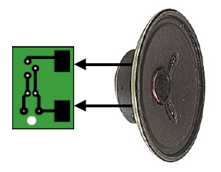
CONNECTING THE SPEAKER


Now connect 2 solid core wires of about 30mm in length to the speaker terminals. Solder the other end to the large copper pads on the underside of the PCB.

POWER SUPPLY
 Left shows how to connect the battery, switch and PCB together.
You will need to either cut the positive lead, or add another wire to link the micro switch to the PCB. It depends how much wire you need.
Connect the power leads by feeding them up through the large hole first, then through the smaller holes.

Share:

TOUCH SWITCHS

TOUCH SWITCH 1

This circuit detects the skin resistance of a finger to deliver a awfully tiny current to the super-alpha try of transistors to show the circuit ON. The output of the "super transistor" activates the BC 557 transistor. The voltage on the highest of the world is passed to the front of the circuit via the 4M7 to require the place of your finger and also the circuit remains ON.

To turn the circuit OFF, a finger on the OFF pads can activate the primary transistor and this may rob the
"super transistor" of voltage and also the circuit can close up.

TOUCH SWITCH 2

This circuit detects the skin resistance of a finger to show the circuit ON for concerning one second. The output are often taken to a counting circuit. The circuit consumes no current when in quiescent mode:

Share:

How to Transform a CD-ROM Drive into a Car CD Player


To be used as CD player, the CD-ROM drive doesn't need to be connected to the computer. This way, it is possible to easily transform a CD-ROM drive into a Car CD player. Sounds crazy? Not so. With this tutorial you will be able to have a CD player in your car without spending almost anything.

The CD-ROM drive to be use may be of any type, from the first models ("1x") until the most modern ones ("60x"). The only prerequisite is that the drive needs to have is an earphone plug and volume control. And practically all CD-ROM drives have that.

There are two great advantages in transforming a CD-ROM drive into a Car CD player. First, who will want to break your car window to take CD-ROM drive? And, secondly, since any type of CD-ROM drive can be used, you may take an old drive that is just dusting away in your house (for instance, a 2x drive from an old 386 computer), which brings the cost down to almost nothing.
To install a CD-ROM drive in the car, you will need a female power plug, to be used to fit into CD-ROM drive power plug (that plug can be cut from an old power supply) and a voltage regulating integrated circuit called 7805, that may be easily found at electronic parts stores. You will also have to buy a heat dissipator for the 7805 (sold at the same store).

The car battery is a 12 V one, but the CD-ROM drive needs two voltages to work: 12 V and 5 V. The 7805 circuit is able to convert a 12 V voltage into 5 V (its pin 1 is for the input, its pin 2 is the grounding, and its pin 3 is the 5 V exit). Figure 1 shows the plan for the connection. The grounding pin should be connected to the wires of the plug grounding and the negative pole of the car battery, what is done by simply connecting that pin to the metallic body of the car.


All you have to do is to make the connections shown in the above schematics (don't forget to isolate all connections with insulating tape) and you are set: you will have a CD-ROM drive working as CD player in your car.
 
The audio output will be made using the earphone plug. To listen to a CD, you will have to use earphones. To have the sound come through the speakers of the car, you will have to buy an amplifier with RCA inputs and a stereo P2 (mini jack) x stereo RCA cable (the same type of cable used to connect Discman units to amplifiers). The stereo P2 plug (also known as mini jack), which is the one used for the earphones, should be fit at the earphone output of the CD-ROM drive, while the RCA plugs should be fit at the input of the amplifier. The volume control will be made using the volume control in the CD-ROM drive.

A last warning: in most CD-ROM drives, the reproduction button (play) and the advance button (skip) are on the same key. In other words, to skip a track, all you have to do is to press the play button.


Share:

Digital Volume Control

This digital volume control has no pot to wear out and introduces almost no noise in the circuit. Instead, the volume is controlled by pressing UP and DOWN buttons. This simple circuit would be a great touch to any home audio project.


Parts:
Part
Total Qty.
Description
C1
1
0.1uf Ceramic Disc Capacitor
U1
1
DS1669 Digital Pot IC (See Notes)
S1, S2
2
Momentary Push Button Switch
MISC
1
Board, Wire, Socket For U1


Notes:
1. U1 is available from Dallas Semiconductor.
2. S1 turns the volume up, S2 turns it down.
3. The input signal should not fall below -0.2 volts.
4. Using a dual polariity power supply (+-5V works fine) will cure most clipping problems. You will have to check the data sheet for the correct pins to connect your voltages.

Share:

Flag

free counters

Popular Posts

CLOCK

TOTAL VISITORS

ONE

Google Map

Recent Posts

Unordered List

  • Lorem ipsum dolor sit amet, consectetuer adipiscing elit.
  • Aliquam tincidunt mauris eu risus.
  • Vestibulum auctor dapibus neque.

Pages

Theme Support

Need our help to upload or customize this blogger template? Contact me with details about the theme customization you need.